Druid Hill Reservoir is a one-billion-gallon (55 acre)potable water storage reservoir that supplies the City of Baltimore and surrounding counties. Druid Reservoir was constructed between 1863 and 1871 and is one of the largest earthen dammed lakes in North America and in 1971 it was named a National Historic Civil Engineering landmark by the American Society of Civil Engineers.
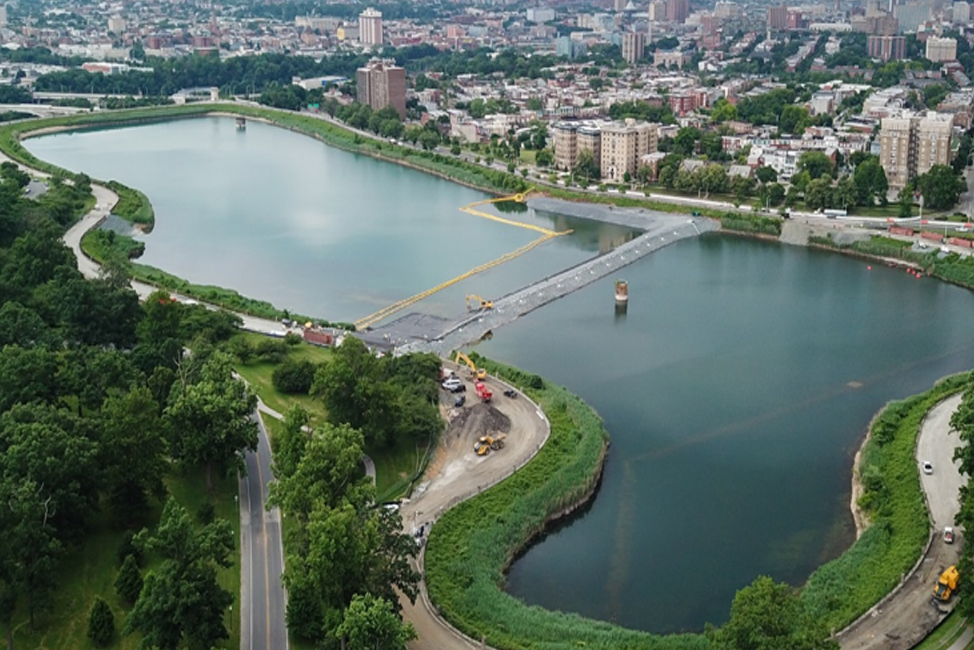
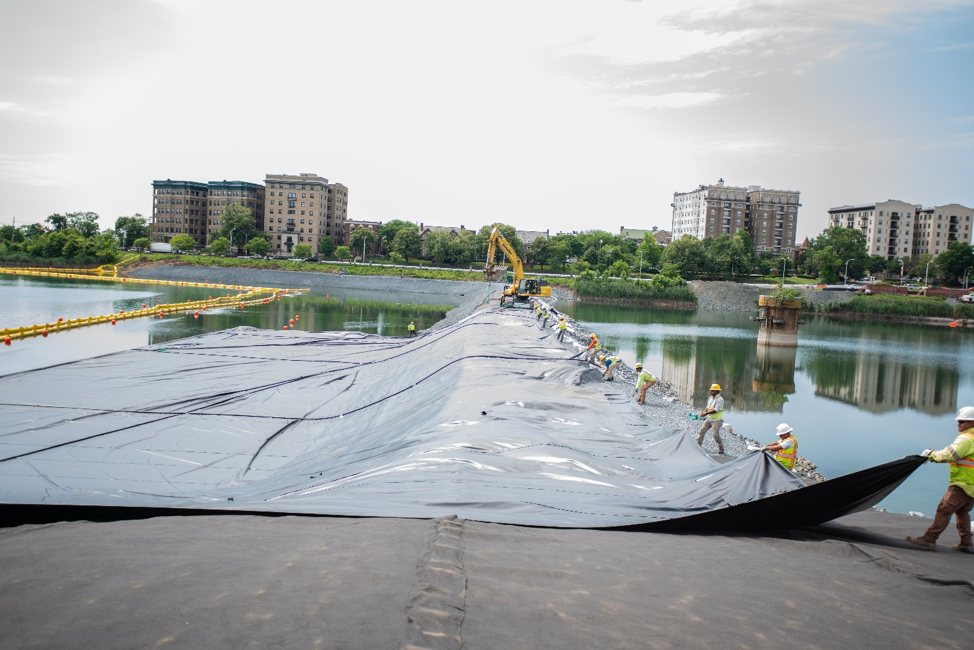
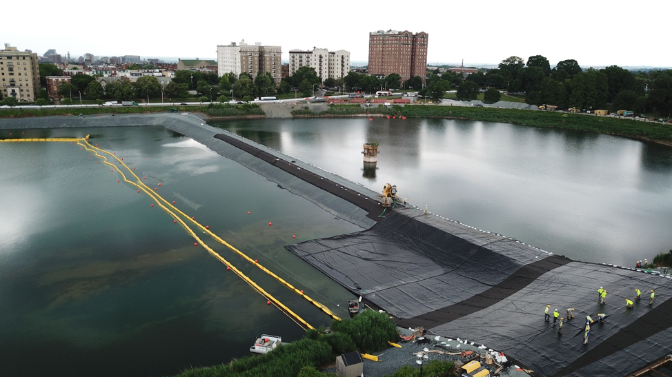
To drain one-half of the reservoir, while maintaining water on the other side, Hallaton lined a 1,200 ft long rockfill berm to create a barrier system instead of driving steel sheetpiles as required in the original bid documents (see Photo One). The water facing side of the rockfill berm was lined with an impermeable geomembrane so water could not flow from the water filled side of the reservoir through the rockfill and into the other half while it was drained to construct underground storage tanks. First a geocomposite was placed on top of the rockfill to protect the reinforced geomembrane during deployment (see Photo Two). Afterwards the factory fabricated reinforced potable water grade geomembrane was installed over the geocomposite and floated out into the reservoir to cover the full length of the rockfill slope that was below water (see Photo 3).
Challenging aspects of this project include:
After stone ballast was placed on top of the completed geomembrane, dewatering started on the western side where the new underground tanks would be constructed (see Photo Four). The western side of the reservoir was completely dewatered to allow for the excavation and construction of the new underground water tanks to create a safe and protected treated water supply for Balitmore (see Photo Four).
Many lessons were learned from this project, including:
Most of the geosynthetics were factory fabricated ahead of time, which increased the speed of the project because time was of the essence. Deploying geomembrane from the top of a cofferdam on one side, while keeping it straight, forward moving, and floating was accomplished much easier using large factory fabricated geomembrane panels (see Photos 2 and 3).
 More projects spotlights
We are a non-profit organization providing education, research, and support for the flexible membrane Industry.